
For the last few years I've used on-board batteries for lighting in my Daylight passenger cars to prevent flickering when rolling through turnouts. Because the passenger cars have 4 wheel trucks only two wheels on each truck are used for power pickup thus flicking occurs passing over the frogs.
I use 1½ volt (GOW) Grain of Wheat bulbs to illuminate the interiors of my passenger cars and cabooses. Each illuminated
car has a 1.28 volt NiMH rechargeable AA or AAA battery and a voltage regulator to keep the battery charged from track power.
To prevent the on-board batteries from discharging slowly over long periods of non use I built a power charging circuit into my control panel to trickle charge the cars with on-board batteries parked on my hidden siding inside my mountain and one storage track in my yard. A pair of mini toggle switches with LED indicators on my control panel remove the operating track voltage and applies the charging current to the sidings for charging. Power to the charger circuit is independent from the control panel power so that the charging circuit can be left on without powering up the control panel/layout.
Initially I installed mini toggle switches under the frames of each passenger car to turn on and off the lights. Getting to the switches has been a real pain in the neck so I eventually went to magnetic latching reed switches glued under the roof and operated with a magnet above the cars. At best the latching switches are a bigger problem than using the toggle switches under the cars. The idea of a latching reed switch is good, they're just not reliable.
I over come the caboose switching problem by installing mini-micro switches glued to the underside of the roof. Rotating the roof vent stack operates the micro switch with a cam.
I finally came up with a better idea to conquer the on and off interior lighting problem in my passenger cars.
My Daylight Passenger cars are pulled by a pair of powered Athearn SD40-2T locomotive frames with Cary E7 A&B shells. I recently purchased a non working E7B locomotive off eBay to be used as a rolling master power supply to power all my illuminated passenger cars. The additional E7B will contain a 5000 mAH 3.7 volt Lithium battery, charger and associated voltage regulators. The E7B power unit will be connected to the passenger cars with micro connectors next to the couplers. I rarely uncouple my Daylight passenger cars and have installed Kadee #119 shelf couplers to prevent accidental uncoupling. By using a female connector on the trailing end of each car and short male pigtail on the lead end I can still remove an individual car easily.


My original intent was to gut the interior of the E7B to make room for a power supply. I had not run into an early Model Power locomotive before I received this one, the eBay listing said "for parts only, non working". The locomotive ran very well when I applied power to it. The eBay listing didn't state the manufacturer of the shell or frame so I was very happy at what it turned out to be, a very good powered locomotive for $9.07. The Model Power frame will hold it's own easily against a Proto 2000 E7 for power and speed with much less motor and gear noise.
I decided to keep the Model Power frame intact for future use and kitbashed a pair of old Athearn PA-1 frames to fit the Cary E7B shell.
1973 Model Power E7B manufactured by Roco
The original Model Power motor has been replaced with a Neodymium magnet can motor.
The Cary shell shown below had nice factory paint with no flaws in the PRR color scheme, very nice for a 40 year old locomotive.

I cut and spliced the square ends of two Athearn PA-1 frames extending their length from 8" to 9 1/16" to fit the Cary shell. I super glued ¼" x .064" K&S brass strips to sandwich both sides of the frame as a splice. Next I drilled, tapped and countersunk two 2 mm flat head screws through the brass strips and frame.


The nice factory paint came off easily after a good soaking in Denatured Alcohol.
After the shell had sufficiently dried I gave it a coat of Rust-Oleum Automotive Primer. I'll airbrush it in Southern Pacific Daylight colors after I've finished installing the electronics.
On to my E7B Power Unit construction:
After I completed the kitbashed E7B frame modification and made sure everything will fit inside I began the construction and custom fit of the electronic circuits and battery.
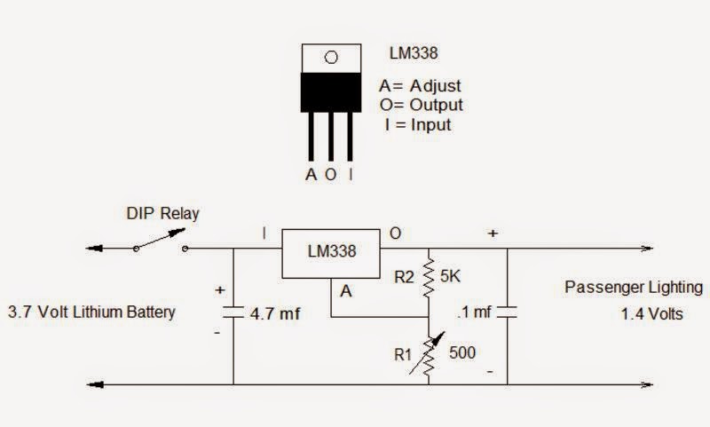
The EMD E7B Dummy Locomotive will house two LM-338T 5 Amp adjustable regulators, Lithium battery charger and battery. The USB TP4056 Lithium battery smart charger circuit boards and 18650 batteries are readily available on eBay.

The regulator above will power the 5 volt in 3.7 volt out USB TP4056 Lithium battery charger from the rails, the other regulator will supply 1.4 volts from the battery to all the passenger car lights.
By careful placement of the TP4056 printed circuit board charger inside E7B shell the red & blue surface mount LED charging indicators can be seen through a shell window for monitoring battery charging.

The 5 volt charging regulator will connect directly to the rails through the six wheel trucks without a switch. The output from the charger card will go direct to the battery. The battery power output is switched with contacts on a mini 5V HK4100F-DC5V-S

I needed heat sinks for both LM 338 regulators, rather than add heat sinks I decided to use the Athearn frame for a heat sink. I drilled and tapped two holes for 2 mm screws to mount the two T0-220 regulators.

The Bridge Rectifier will provide the correct polarity to the 5 volt Regulator from the rails.


The picture below shows the completed battery power supply with both regulators. The Athearn PB frame has a shorter fuel tank than a E7B so I filled the space with a leftover tank from an earlier kitbash project.


As you can tell the circuit board is very small but charges the battery at 1.2 amps. Painting the Cary shell is next.


I added labels the bottom of the fuel tank with decals for the voltage test points and the two adjustment potentiometer so that the regulators can be adjusted without removing the shell.
My E7B Battery Lighting Locomotive is finished and it works better than planned, the two LM338 voltage regulators are extremely stable.
No comments:
Post a Comment