
Because I use 12 volt Grain of Wheat bulbs in all of my structures and the Arduino doesn't have a high enough current rating to switch the 40ma to 100ma 12 volt bulbs I needed a high current driver. Even though I operate the GOW bulbs at reduced voltage the current is too high for an Arduino to drive the bulbs directly.
I searched for a high current IC driver chip and first went with a Toshiba TD62304AP seven channel chip. The Toshiba chip is non inverted it required the Arduino Sketch to be inverted. That meant having two sketches, one normal for driving LEDs direct from the Arduino and a reversed sketch for driving the high current ICs.
As time passed the price of Toshiba TD62304AP has more than tripled in price making it necessary to find a lower cost chip. I noticed that many Arduino users were using a ULN2003AP chip as a high current driver and after some research I found it to have the same current handling capacity as the TD62304 and that it would be a good replacement, even better the ULN2003 is inverted.
My original sketch was for driving 14 outputs because the house I was going to be using had 14 GOW bulbs. When I got into larger houses I decided to use all of the Arduino UNO outputs and increased it to 20 ports. As I have several houses with 14 bulbs and several with up to 20 bulbs. I ended up making two types of Arduino extension boards that plug onto the UNO, one with two 16 pin sockets for two UNL2003 chips and the other with three 16 pin sockets to hold three ULN2003s.
I went with a "Prototype PCB for Arduino UNO R3 Shield Board DYI Breadboard" off eBay (US Seller) for my expansion boards.

The picture below shows a finished 14 port high current driver board.

The chips are ULN2003APG, 500ma Sinking Capacity per channel.
This is a finished 20 port driver expansion board with three ULN2003APG chips installed.

The board on the left is the finished underside or wiring side of the 20 port driver board. I used standard resistor color code for the wiring. The wiring is #28 AWG stranded, the bare wire is also #28.
This is a CAD drawing of a 14 port expansion board.


I use 16 conductor #28 AWG Flat Ribbon wire for the 14 port controllers and 26 conductor for the 20 port. I parallel 2 wires for the 14 port and 4 wires in the 20 port to increase the current carrying handling capacity of the ribbon cable.
Arduino Code for the High Current Driver Boards
Because the 20 port sketch works for both the 14 port and 20 port versions driver cards I decided to go with the 20 port sketch in all of my Arduinos. I can't tell the difference between the 14 and 20 port when they're operating.
This is the code for the 20 port controller
#define numleds 20
byte ledpins [ ] = { 0,1,2,3,4,5,6,7,8,9,10,11,12,13,14,15,16,17,18,19 } ;
void setup( ) {
randomSeed(analogRead(0));
for ( int i=0; i <= numleds; i++ ) {
pinMode ( ledpins [ i ], OUTPUT) ;
delay (5);
digitalWrite ( ledpins [ i ] , LOW) ;
}
}
void loop ( ) {
digitalWrite ( ledpins [ random ( 0, numleds+1 ) ], lightsw ( ) ) ;
delay ( 5000 ) ;
}
boolean lightsw ( ) {
if ( random (5,100) > 60 ) return HIGH ;
else return LOW ;
}
===================================================
Arduino Code for direct LED Drive (Inverted)
#define numleds 20
byte ledpins [ ] = { 0,1,2,3,4,5,6,7,8,9,10,11,12,13,14,15,16,17,18,19 } ;
void setup( ) {
randomSeed(analogRead(0));
for ( int i=0; i <= numleds; i++ ) {
pinMode ( ledpins [ i ], OUTPUT) ;
delay (5);
digitalWrite ( ledpins [ i ] , HIGH) ;
}
}
void loop ( ) {
digitalWrite ( ledpins [ random ( 0, numleds+1 ) ], lightsw ( ) ) ;
delay ( 5000 ) ;
}
boolean lightsw ( ) {
if ( random (5,100) > 60 ) return LOW ;
else return HIGH ;
}
===================================================
Random lighting test code:
This Sketch is for testing the ports and load for proper operation. It begins with all ports activated for 5 seconds then sequences the ports for one second on with a ½ second delay off.
void setup(){
pinMode(0, OUTPUT);
pinMode(1, OUTPUT);
pinMode(2, OUTPUT);
pinMode(3, OUTPUT);
pinMode(4, OUTPUT);
pinMode(5, OUTPUT);
pinMode(6, OUTPUT);
pinMode(7, OUTPUT);
pinMode(8, OUTPUT);
pinMode(9, OUTPUT);
pinMode(10, OUTPUT);
pinMode(11, OUTPUT);
pinMode(12, OUTPUT);
pinMode(13, OUTPUT);
pinMode(14, OUTPUT);
pinMode(15, OUTPUT);
pinMode(16, OUTPUT);
pinMode(17, OUTPUT);
pinMode(18, OUTPUT);
pinMode(19, OUTPUT);
}
void loop(){
digitalWrite(0, HIGH);
digitalWrite(1, HIGH);
digitalWrite(2, HIGH);
digitalWrite(3, HIGH);
digitalWrite(4, HIGH);
digitalWrite(5, HIGH);
digitalWrite(6, HIGH);
digitalWrite(7, HIGH);
digitalWrite(8, HIGH);
digitalWrite(9, HIGH);
digitalWrite(10, HIGH);
digitalWrite(11, HIGH);
digitalWrite(12, HIGH);
digitalWrite(13, HIGH);
digitalWrite(14, HIGH);
digitalWrite(15, HIGH);
digitalWrite(16, HIGH);
digitalWrite(17, HIGH);
digitalWrite(18, HIGH);
digitalWrite(19, HIGH);
delay(5000);
digitalWrite(0, LOW);
digitalWrite(1, LOW);
digitalWrite(2, LOW);
digitalWrite(3, LOW);
digitalWrite(4, LOW);
digitalWrite(5, LOW);
digitalWrite(6, LOW);
digitalWrite(7, LOW);
digitalWrite(8, LOW);
digitalWrite(9, LOW);
digitalWrite(10, LOW);
digitalWrite(11, LOW);
digitalWrite(12, LOW);
digitalWrite(13, LOW);
digitalWrite(14, LOW);
digitalWrite(15, LOW);
digitalWrite(16, LOW);
digitalWrite(17, LOW);
digitalWrite(18, LOW);
digitalWrite(19, LOW);
digitalWrite(0, HIGH);
delay(1500);
digitalWrite(0, LOW);
delay(500);
digitalWrite(1, HIGH);
delay(1500);
digitalWrite(1, LOW);
delay(500);
digitalWrite(2, HIGH);
delay(1500);
digitalWrite(2, LOW);
delay(500);
digitalWrite(3, HIGH);
delay(1500);
digitalWrite(3, LOW);
delay(500);
digitalWrite(4, HIGH);
delay(1500);
digitalWrite(4, LOW);
delay(500);
digitalWrite(5, HIGH);
delay(1500);
digitalWrite(5, LOW);
delay(500);
digitalWrite(6, HIGH);
delay(1500);
digitalWrite(6, LOW);
delay(500);
digitalWrite(7, HIGH);
delay(1500);
digitalWrite(7, LOW);
delay(500);
digitalWrite(8, HIGH);
delay(1500);
digitalWrite(8, LOW);
delay(500);
digitalWrite(9, HIGH);
delay(1500);
digitalWrite(9, LOW);
delay(500);
digitalWrite(10, HIGH);
delay(1500);
digitalWrite(10, LOW);
delay(500);
digitalWrite(11, HIGH);
delay(1500);
digitalWrite(11, LOW);
delay(500);
digitalWrite(12, HIGH);
delay(1500);
digitalWrite(12, LOW);
delay(500);
digitalWrite(13, HIGH);
delay(1500);
digitalWrite(13, LOW);
delay(500);
digitalWrite(14, HIGH);
delay(1500);
digitalWrite(14, LOW);
delay(500);
digitalWrite(15, HIGH);
delay(1500);
digitalWrite(15, LOW);
delay(500);
digitalWrite(16, HIGH);
delay(1500);
digitalWrite(16, LOW);
delay(500);
digitalWrite(17, HIGH);
delay(1500);
digitalWrite(17, LOW);
delay(500);
digitalWrite(18, HIGH);
delay(1500);
digitalWrite(18, LOW);
delay(500);
digitalWrite(19, HIGH);
delay(1500);
digitalWrite(19, LOW);
delay(500);
}
===================================================
A simple copy and paste to the Arduino IDE should work perfect for the Sketches.
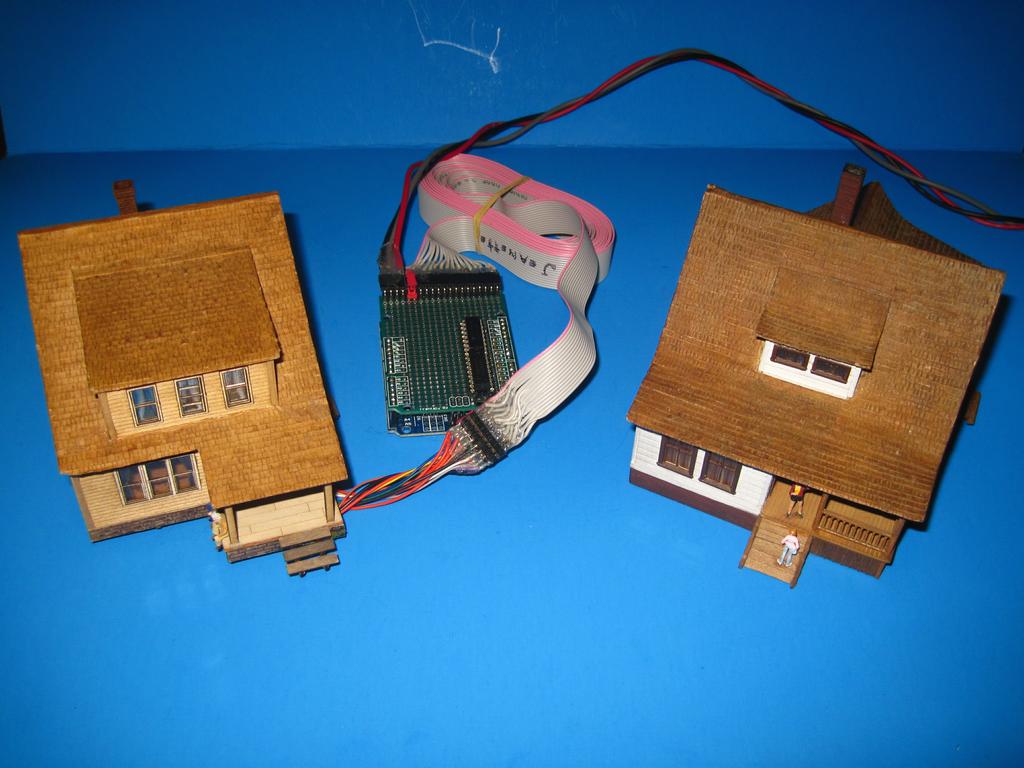
Two existing houses modified for Arduino lighting.
.
No comments:
Post a Comment