
=================================================================
There is a new updated Sketch toward the end of this post adding six more outputs making it a 20 port light controller.
Updated October 10, 2018:
I added a Test Connector and Sketch to check the operation of the high current driver chips.
Original Post August, 2016
I did a redesign of my random light controller sketch and expansion board from 12 to 14 outputs. This is the 14 output sketch:
================
#define numleds 14
byte ledpins [ ] = { 0,1,2,3,4,5,6,7,8,9,10,11,12,13 } ;
void setup( ) {
for ( int i=1; i <= numleds; i++ ) {
pinMode ( ledpins [ i ], OUTPUT) ;
digitalWrite ( ledpins [ i ] , HIGH) ;
}
}
void loop ( ) {
digitalWrite ( ledpins [ random ( 0, numleds+1 ) ], lightsw ( ) ) ;
delay ( 4000 ) ; // 4000 = 4 seconds
}
boolean lightsw ( ) {
if ( random (0,100) > 60 ) return LOW ;
else return HIGH ;
}
================
Sketch uses 2,130 bytes (0%) of program storage space. Maximum is 253,952 bytes.
Global variables use 27 bytes (0%) of dynamic memory, leaving 8,165 buyes for local variables. Maximum is 8,192 bytes.
=================
The only difference to the expansion board is wiring up the 7th output of each chip, all 14 outputs of the driver chips are used.
--------------------------------------------------------------------------------
I decided to make a random lighting controller for my structures. The Arduino UNO micro processor is perfect for my project. The cost is very low due to the Arduino being "Open Architecture". The Arduino can drive 14 output ports, each port can deliver 20ma at 5 volts. That is the max current available and posts on the Internet say 'to be on the safe side keep the current below 15ma per port".
I rarely operate me LEDs over 10ma so I'm in the "Safe Zone". I also have many structures with 12 volt incandescent bulbs for lighting. The 12 volt incandescent bulbs can draw anywhere from 40 to 100ma at 12 volts, I operate my 12 volt bulbs in the vicinity of 9 volts for longer life but mainly for realism. A small incandescent bulb operating near max voltage doesn't look very realistic, toy like to me.
To obtain a higher current output from the UNO I came up with a simple 500ma per channel driver chip. It is rather a simple project again because of the Arduino open architecture. The UNO will direct drive the TD62304AP seven channel driver chip. The UNO 5 volt regulator will provide the power to the logic side of the driver chip and the driver outputs will switch the ground side of the lighting with an input from 1 to 50 volts at up to 500ma per channel.
Each channel of the driver chip requires .320ma from the UNO, as there is such little current needed from the UNO if you would like to monitor the outputs LEDs can also be used directly from the UNO outputs. My design allows for monitoring.
To get started on this project here is what you need.

The UNO Expansion Boards come in several versions, most come with the Arduino connectors. This particular board has paired links that make building this driver circuit easier. This board has a part number of 64502SP13-10.
I haven't been able to find it with that number, only with "paired links". Cost of this board is between 2 for $5 and 4 for $8 from this eBay seller.
http://www.ebay.com/itm/4x-Prototype-PCB-for-Arduino-UNO-R3-Shield-Board-DIY-/252852761647?hash=item3adf32f42f:g:nrUAAOSwAL9UcMmL
The TD62304AP Driver chips are also available on eBay under $2. The 16 pin DIP sockets are available at any electronic store (Radio Shack).
I normally buy almost all of my electronic parts in bulk off eBay.
I buy the single row 40 pin .1"/.254mm breakable sockets off eBay. The sockets can be used for either male or female connectors. For a better male fit to the socket I buy the male header strips, the pins are a bit larger in diameter and fit tighter into the sockets.
I worked up a CAD drawing of the UNO expansion board.
When wiring the expansion board the output terminals are not in order, Pin 0 is output #1 then it skips #1 & #2. Pins #3 through Pin #13 are outputs #2 through #14.

This is my finished controller.
The 16 pin micro strip connector at the bottom is the UNO processor switched ground outputs 1 through 14 (Max 20ma each port, to protect heat build up I would recommend a Max of 15ma per port), Pin #15 is -5 volts or ground & Pin #16 is +5 volts. This connector can drive LEDs directly.

The 16 pin strip above the chips is the high current switched ground (500MA). Pins 1 through 14 are the high current lamp drivers, pin 16 goes to the red terminal block screw, any DC voltage from 1 to 50 volts.
You can do a copy and paste to your Arduino UNO and you're in business.
By changing the number in red you can change the delay portion of the sketch. I like my on off duration long.
All in all this project is one of my very best, I have three random light controllers in operation and working driving three triple story houses.
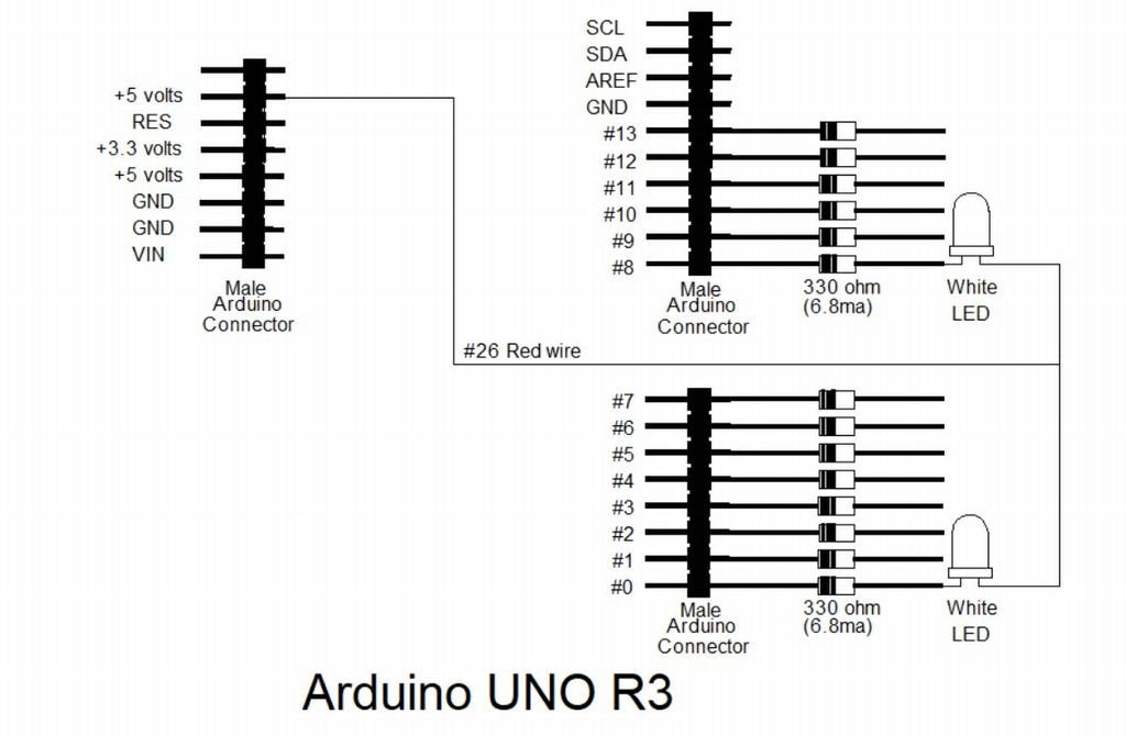
Update: For those that want to use 14 LEDs here is a simple wiring diagram.
September 28, 2017 Update:
The drawings below are revamped for a simple high current driver with a single 20 pin 90° angle Arduino connector.
This version uses a standard Arduino expansion board, not the paired board above. I buy these off eBay from Electronics Salon.

The pins on the driver chips are wired from 1 to 7 on IC-1 to the 20 pin connector pins 1 to 7. IC-2 pins 1 to 7 to the 20 pin connector pins 8 to 14.
The ICs need a 5 volt supply for the internal logic from either the Arduino +5V or an external source on pin 17.
Because I'm using #28 gauge ribbon cable between the Arduino UNO and the house lighting I doubled up the the 8½ volt supply wires (pins 15 & 16) to carry the full load of 550ma to all 14 bulbs.
Five wires to the 16 pin connector (yellow, green, blue, violet & grey) go through the board and are soldered direct to the connector pins so that the board will clear the USB connector on the UNO, very close fit.

Arduino Uno Expansion board, Wiring side ↑ Top of board ↓

As Built Arduino UNO High Current Driver Expansion Boards.
Getting in deeper with the Arduino programming I have improved my Random Lighting Controller. With the help of some Model Railroad Forum members I have refined the Arduino Sketch for better operation. The new Sketch below can be copy and paste to an UNO, no wiring changes are necessary.
++++++++++++++++
#define numleds 14
byte ledpins [ ] = { 0,1,2,3,4,5,6,7,8,9,10,11,12,13 } ;
void setup( ) {
randomSeed(analogRead(0));
for ( int i=0; i <= numleds; i++ ) {
pinMode ( ledpins [ i ], OUTPUT) ;
digitalWrite ( ledpins [ i ] , HIGH) ;
}
}
void loop ( ) {
digitalWrite ( ledpins [ random ( 0, numleds+1 ) ], lightsw ( ) ) ;
delay ( 5000 ) ;
}
boolean lightsw ( ) {
if ( random (5,150) > 60 ) return LOW ;
else return HIGH ;
}
++++++++++++++++
The above Sketch will make the lighting truly random with longer on and off timing.
I have increased my Arduino UNO Light Controller to 20 ports. The pictures below are the high current driver expansion boards.
I added a third high current driver chip (TD62304AP) to the expansion board.


The sketch below has been updated to 20 ports.
++++++++++++++++
Update October 18, 2017
I have increased my Arduino UNO Light Controller to 20 ports. The pictures below are the high current driver expansion boards.
I added a third high current driver chip (TD62304AP) to the expansion board.
I
modified a duel row Arduino connector adding an additional 8 contacts.
The weird connector will accommodate the 6 additional ports plus a
spare (7) and one for power.
Because
the driver chip is 7 channel I included a port for the 7th output even
though the Arduino UNO R3 doesn't have the capacity for the 7th output
on the driver chip. The 8th pin is power, that will help prevent
voltage drop for the additional load.
To obtain the additional 6 ports the Sketch requires adding the 6 Analog inputs as outputs on the UNO.
To accommodate the 6 added ports I came up with a Mel connector made from dual row 16 pin Arduino angle connector (32 pins). I cut off 8 pins from the dual 16 pin connector to end up with a 24 pin.

The 16 conductor cable works great for a 14 port controller, I doubled the power wiring to support full current load of 600ma.

I went with a 26 conductor flat ribbon cable for the 20 port controller. I used 5 wires out of the the 26 as 8½ volt supply power. With all the bulbs on the main power will be 1 amp. The ribbon cable is #28 AWG wire rated at 230ma Circular Mils X 5 #28 wires = #16 AWG at 3.7 amps.
To accommodate the 6 added ports I came up with a Mel connector made from dual row 16 pin Arduino angle connector (32 pins). I cut off 8 pins from the dual 16 pin connector to end up with a 24 pin.
The 16 conductor cable works great for a 14 port controller, I doubled the power wiring to support full current load of 600ma.
I went with a 26 conductor flat ribbon cable for the 20 port controller. I used 5 wires out of the the 26 as 8½ volt supply power. With all the bulbs on the main power will be 1 amp. The ribbon cable is #28 AWG wire rated at 230ma Circular Mils X 5 #28 wires = #16 AWG at 3.7 amps.
++++++++++++++++
The sketch below has been updated to 20 ports.
++++++++++++++++
#define numleds 20
byte ledpins [ ] = { 0,1,2,3,4,5,6,7,8,9,10,11,12,13,14,15,16,17,18,19 } ;
void setup( ) {
randomSeed(analogRead(0));
for ( int i=0; i <= numleds; i++ ) {
pinMode ( ledpins [ i ], OUTPUT) ;
digitalWrite ( ledpins [ i ] , HIGH) ;
}
}
void loop ( ) {
digitalWrite ( ledpins [ random ( 0, numleds+1 ) ], lightsw ( ) ) ;
delay ( 6000 ) ;
}
boolean lightsw ( ) {
if ( random (5,150) > 60 ) return LOW ;
else return HIGH ;
}
++++++++++++++++
The board wiring for the third driver chip to the connector is straight forward adding ports 14 - 19. The Arduino UNO will except 14 -19 programming for A0-A5 ports

Notice the third IC is inverted, that made the wiring much simpler. The IC to board connector wiring is color coded.
Because of the 6 additional ports I also made some minor changes to the timing.
All in all I'm very impressed with the improved operation of the Random Lighting Controller.
Update October 10, 2018
Because of the random operation of the controller I needed a way to check the high current driver board. I made a plug that plugs onto the driver board connector with 20 2mm 12 volt Grain of Wheat bulbs. Using ⅛" copper foil Tape for the bulb voltage source I soldered the bulbs to the connector. Pins 15 & 16 are voltage in, in my case 8½ volts.


The copper foil tape made it easy to solder the bulbs to the connector.
I wrote a program to illuminate all 20 bulbs for 5 seconds then sequence them individually.
Here is my sketch:
void setup(){
pinMode(0, OUTPUT);
pinMode(1, OUTPUT);
pinMode(2, OUTPUT);
pinMode(3, OUTPUT);
pinMode(4, OUTPUT);
pinMode(5, OUTPUT);
pinMode(6, OUTPUT);
pinMode(7, OUTPUT);
pinMode(8, OUTPUT);
pinMode(9, OUTPUT);
pinMode(10, OUTPUT);
pinMode(11, OUTPUT);
pinMode(12, OUTPUT);
pinMode(13, OUTPUT);
pinMode(14, OUTPUT);
pinMode(15, OUTPUT);
pinMode(16, OUTPUT);
pinMode(17, OUTPUT);
pinMode(18, OUTPUT);
pinMode(19, OUTPUT);
}
void loop(){
delay(5000);
digitalWrite(0, HIGH);
digitalWrite(1, HIGH);
digitalWrite(2, HIGH);
digitalWrite(3, HIGH);
digitalWrite(4, HIGH);
digitalWrite(5, HIGH);
digitalWrite(6, HIGH);
digitalWrite(7, HIGH);
digitalWrite(8, HIGH);
digitalWrite(9, HIGH);
digitalWrite(10, HIGH);
digitalWrite(11, HIGH);
digitalWrite(12, HIGH);
digitalWrite(13, HIGH);
digitalWrite(14, HIGH);
digitalWrite(15, HIGH);
digitalWrite(16, HIGH);
digitalWrite(17, HIGH);
digitalWrite(18, HIGH);
digitalWrite(19, HIGH);
digitalWrite(0, LOW);
delay(1500);
digitalWrite(0, HIGH);
delay(500);
digitalWrite(1, LOW);
delay(1500);
digitalWrite(1, HIGH);
delay(500);
digitalWrite(2, LOW);
delay(1500);
digitalWrite(2, HIGH);
delay(500);
digitalWrite(3, LOW);
delay(1500);
digitalWrite(3, HIGH);
delay(500);
digitalWrite(4, LOW);
delay(1500);
digitalWrite(4, HIGH);
delay(500);
digitalWrite(5, LOW);
delay(1500);
digitalWrite(5, HIGH);
delay(500);
digitalWrite(6, LOW);
delay(1500);
digitalWrite(6, HIGH);
delay(500);
digitalWrite(7, LOW);
delay(1500);
digitalWrite(7, HIGH);
delay(500);
digitalWrite(8, LOW);
delay(1500);
digitalWrite(8, HIGH);
delay(500);
digitalWrite(9, LOW);
delay(1500);
digitalWrite(9, HIGH);
delay(500);
digitalWrite(10, LOW);
delay(1500);
digitalWrite(10, HIGH);
delay(500);
digitalWrite(11, LOW);
delay(1500);
digitalWrite(11, HIGH);
delay(500);
digitalWrite(12, LOW);
delay(1500);
digitalWrite(12, HIGH);
delay(500);
digitalWrite(13, LOW);
delay(1500);
digitalWrite(13, HIGH);
delay(500);
digitalWrite(14, LOW);
delay(1500);
digitalWrite(14, HIGH);
delay(500);
digitalWrite(15, LOW);
delay(1500);
digitalWrite(15, HIGH);
delay(500);
digitalWrite(16, LOW);
delay(1500);
digitalWrite(16, HIGH);
delay(500);
digitalWrite(17, LOW);
delay(1500);
digitalWrite(17, HIGH);
delay(500);
digitalWrite(18, LOW);
delay(1500);
digitalWrite(18, HIGH);
delay(500);
digitalWrite(19, LOW);
delay(1500);
digitalWrite(19, HIGH);
delay(500);
}
Each bulb will be on for 1½ seconds and off for a ½ second.
No comments:
Post a Comment