.

Welcome to My HO Model Railroad Blog

January 17, 2015 Micro Connectors

This post is an update on micro connectors.

After I finished my major track repair I was routinely checking my locomotive fleet to make sure everything would work without problems.  I found problems but not what I expected.  The track repair worked great but I found several locomotives that developed problems sitting on my display shelves.  One problem was with a piece of MOW equipment, my snow blower.  The Proto F7B Snail had developed cracked axle gears in storage so it was overhaul time.

After replacing the Proto axle gears with Athearn gears it was happy again but in the process I discovered it had Deans connectors between the Athearn Snow Blower and the Proto Snail.  Well that is something that needs correcting.  Years ago when I couldn't find micro connectors I used Deans but now I have a parts drawer full of micro connectors.


I now use micro connectors on all of my model railroad equipment, the key to micro connectors was finding them.  They are easily found on eBay as 2.54mm 40 Pin Connector Strips for single row and Dual Row 2.54mm 40 Pin Connector Strips for making the 8 Pin NMRA DCC connectors.

Single Row 2.54mm 40 Pin Connector Strips
 

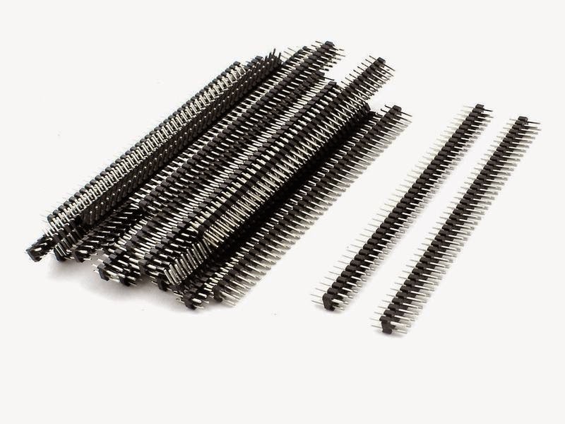
Double Row 2.54mm 40 Pin Male Header Strips

They cut easily using an Atlas #400 Super Saw.

So now on to replacing the Deans connectors.

The picture above shows my Proto F7B Snail, my somewhat kitbashed Athearn Snow Blower and an assortment of micro connector strips. 

The Athearn Snow Blower out of it's Blue Box is too long for an SP snow blower, I remove two riveted sections making it 42' long.  I also added a gear motor to turn the snow blade.  The gear motor and warm white LED headlight are connected to a DCC decoder in the Snail with a three pin connector.


The picture above shows the micro connector strips with some cut sections ready for use.  The small 8 pin connector on the left is a Printed Circuit board header the others are Female on one side and Male on the other side.  The size of the squares on the cutting mat are ½".

The pictures below show the connectors in the Snail.


Using a connector between the motor and rails also makes makes it easier to work on the motor using a connectorized cable from a bench power supply.


With connectors a bench power supply can plug directly into the motor for testing and lubing.

I used a single pin connector to connect the wires to the snowblade gear motor, by reversing the connectors the direction of blade can be reversed.


The 2 pin connector on the right is for the snow blower headlight.

The 3 pin male connector on the bottom of the snow blower connects to a female pigtail from the Snail DCC decoder, headlight is standard headlight on off and Function 3 controls the snow blade motor.

By using the micro connectors everything is super simple to work on and especially helpful at the low cost when buying in bulk off eBay, a typical single row 40 pin strip cost less than a dollar and a dual row 80 pin strip is only a few pennies more.  One 80 pin strip will make 10 NMRA DCC connectors for less than 15¢ each.


January 11, 2015 Code 100 track to Code 83 the easy way

I ran into a difficult situation in a hard to get to spot on my layout while doing some repair work on my track.  You all know Murphy's Law, "Anything that can go wrong, will go wrong."

I needed to replace a turnout in the mouth of a tunnel at a tunnel portal, it gets worse, the tunnel portal is below a Howe Truss bridge.  As Murphy's Law says it gets even worse.  I use code 100 track inside my mountains for more reliability and code 83 track where it is viewable.  Naturally the transition from 100 to 83 is at the turnout that I need to replace because both tracks from the turnout are leaving the mountain through the tunnel portal.

There is nothing worse in doing track work than installing an Atlas transition rail joiner other than having to do it in a extremely hard to get to location.  I decided to try a different way this time, I made my own transitions.

I started out by clamping a small piece of code 100 track in my Panavice and using a 8" metal file on the rails as in the pictures below.  I'm using leftover pieces of track before I cut up a new turnout.


I filed an ⅛" gap from the top of the code 100 rails down to the bottom rail flange leaving .017" of the bottom rail as a shelf for the code 83 rail to rest on.


The picture above shows the code 100 rail on the left with the code 83 rail in place resting on the .017" shelf.


I hadn't planned on beveling the rail ends but I gave it a try and it worked, the rails slipped easily together inside a standard Atlas code 100 rail joiner as shown in the picture below.


I was planning to solder the joint but it wasn't necessary, the track fit together perfectly and the pressure from the tight connection inside the joiner holds everything in very good alignment as well as a good electrical connection.

This process worked out so good and so easy it was much easier to replace the turnout.  I filed the gaps in the new turnout and beveled the bottom of the code 83 rails and the turnout slipped in very nicely.

I don't think I'll ever use a store bought transition joiner again.
 

January 10, 2015 Modifying an Atlas Turnout

This post is about a modification to an Atlas Snap Switch turnout for improved performance.

In my original layout design and construction all of my viewable turnouts were Atlas code 83 purchased in the late 1980s.   I have changed my preference to Peco turnouts recently mainly because I'm really impressed with the Peco spring lock points.

It's a very simple idea and keeps the moving rail points firmly closed.  The only downside to a Peco turnout is that their under the layout switch motor requires a 2¼" hole under the points.  However I also like the Peco switch motor better than the rest of the available switch motors, low current and high power.


The picture above shows the Peco locking spring, the picture below is a Peco PL-10 switch machine.


All of my Atlas turnouts use under the layout switch motors, the Atlas ATL65 has a 1" throw arm and is marginal at best.  Operating the throw arm at 1" it must be exactly centered under the turnout or it will not be reliable.  The picture below is an Atlas ATL65 below the layout switch machine.


I saw a post on one of the model railroad forums where a fellow added a spring to his Atlas turnouts and I decided to give it a shot.


First I cut away a 1/32" recess a ½" long from the fixed tie next to the moving throw arm.  This will give the spring room to move freely.  

I duplicated the Peco spring using .015" piano wire.  I bent a ¼" leg then the ¼" V with a second ¼" leg.  


I drilled a #74 hole in the moving tie slightly offset from the throw arm hole, placement of this hole isn't too critical.  The hole in the fixed tie is critical!  Move the throw arm fully in both directions making a slight scratch in the recessed cut area of the fixed tie to mark where hole in the moving throw arm ends up.  Those marks are extremely critical.  Next drill a #74 hole in the center of the fixed tie exactly centered between the two marks.  That will be the center balance point for the spring pressing the points against the outside rails. 

Next insert the spring and check for smooth operation.  To keep the spring in the holes glue a strip of styrene across the recessed area making sure the spring moves easily.  Flush cut the spring legs after the glue has dried.

This modification makes the Atlas Snap Switch a real snap switch.  I always thought it was funny that a Peco turnout snapped and a Atlas Snap Switch didn't.


Next cut off the center mounting tabs and bend over the side tabs.  I used Super Glue to attach the Peco Switch Motor to the bottom of the Atlas turnout.


I used a short pigtail with a three pin connector on the Peco switch motor because the terminals are solder type.


The real Atlas Snap Switch with the Peco PL-10 Switch Motor is ready to go.


The above picture shows the modified Atlas turnout in place.  The 25 year old original turnout turned brittle and needed replacing.

Using a short pigtail with a connector simplifies testing and installation with the switch motor mounted directly to the turnout.  The Atlas switch motors are connected with screw terminals, the Peco motors have solder terminals.